SEZAMOR sp. z o.o.

The radial davits of series ŻZW, with adjustable outreach, are designed for handling of small cargos on board the sea-going vessels of unlimited region of navigation. The davits can be operated at rated hoisting capacity under conditions of vessel's heel up to 5° to either side and trim up to 2° whereas the slewing gear can be operated at vessel's heel up to 5° and trim to 5°.
The davit consists of:
Slewing of davit is performed by means of electric drive, or emergency, manually by means of the crank handle. Special coupling insert protects the davit against simultaneous slewing with both types of drive being applied. Maximum slewing angle amounts to + 135° with regard to davit normal working position. Slewing duration in the angle range from - 135° to + 135°, with electric drive applied, amount to 60 seconds. Cargo hoisting speed at rated capacity amounts to about 10 m/min. Capacity of rope drum of hoisting gear winch equals 40m of wire rope thus enabling hoisting of cargo onto hight of 40 m.
The davit is controlled with portable control cassette.
The davit is delivered in assembled condition with winches, rigging and blocks, foundation, electric installation and electric drive as appropriately preserved.
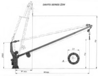
Davit with adjustable outreach ŻZW Q - Wmin / Wmax - '35' (or '46') 'P' (or 'L')
where:
Q - rated hoisting capacity [t];
Wmin - minimum outreach of davit [m];
Wmax - maximum outreach of davit [m];
H - height of davit [m];
'35' (or '46') - description of electric drive of rope winch
'35'-3x 380V/50 Hz;
'46' - 3 x 440 V/60 Hz;
'P' (or 'L') - designation of structural variation:
'P' - right-hand make;
'L'- left-hand make;
| Denotation of Davit | Hoisting capacity | Minimum outreach | Maximum outreach | Height at Wmin | Height at Wmax | Weight approx. |
|---|---|---|---|---|---|---|
| Q [t] | Wmin [m] | Wmax [m] | Hp [m] | Hp [m] | P [kg] | |
| ŻZW 0.45-2.15/6.5 | 0.45 | 2.15 | 6.50 | 7.15 | 2.50 | 1440 |
| ŻZW 0.45 - 2.2/6.75 | 0.45 | 2.20 | 6.75 | 7.33 | 2.60 | 1460 |
| ŻZW 0.45 - 2.2/7.0 | 0.45 | 2.20 | 7.00 | 7.33 | 2.70 | 1480 |
| ŻZW 0.45 - 2.2/7.25 | 0.45 | 2.20 | 7.25 | 7.44 | 2.80 | 1500 |
| ŻZW 0.45 - 2.3/7.5 | 0.45 | 2.30 | 7.50 | 7.55 | 2.85 | 1520 |
| ŻZW 0.45 - 2.4/7.75 | 0.45 | 2.40 | 7.75 | 8.00 | 3.00 | 1540 |
| ŻZW 0.45 - 2.4/8.0 | 0.45 | 2.40 | 8.00 | 8.00 | 3.10 | 1560 |
| ŻZW 0.40 - 2.6/8.25 | 0.40 | 2.60 | 8.25 | 8.65 | 3.20 | 1580 |
| ŻZW 0.40 - 2.6/8.5 | 0.40 | 2.60 | 8.50 | 8.65 | 3.25 | 1600 |
| ŻZW 0.40 - 2.65/8.75 | 0.40 | 2.65 | 8.75 | 8.85 | 3.35 | 1620 |
| ŻZW 0.40 - 2.65/9.0 | 0.40 | 2.65 | 9.00 | 9.20 | 3.45 | 1640 |
| ŻZW 0.30 - 2.8/9.25 | 0.30 | 2.80 | 9.25 | 9.30 | 3.55 | 1660 |
| ŻZW 0.30 - 2.9/9.5 | 0.30 | 2.90 | 9.50 | 9.65 | 3.65 | 1680 |
| ŻZW 0.30 - 2.9/9.75 | 0.30 | 2.90 | 9.75 | 9.65 | 3.75 | 1700 |
| ŻZW 0.30-3.0/10.0 | 0.30 | 3.0 | 10.0 | 10.00 | 3.85 | 1720 |
D - foundation bolt location diameter 540 mm;
D1 - foundation outer diameter 620 mm;
d - diameter of 8 holes for foundation bolts 26 mm